Sailing Upwind
![]()
![]()
This article derives, from basic physics, the angle that maximises upwind progress of an idealized dinghy.
Why sailing upwind is counterintuitive
Sailing directly into the wind is impossible: the forces push the boat backwards. For most dinghies, the region within about 45° of the wind is called the no-go zone — the sail just flaps and generates no drive.
Yet if the destination is dead upwind the boat can still reach it by tacking — zig-zagging on alternating close-hauled legs, like a car reversing into a tight parking space. The question is how wide to make the zig-zags.
Sail too close to the wind ($\theta$ small) and the boat barely moves. Bear away too far ($\theta$ large) and the boat is fast but pointing mostly sideways — lots of distance covered, very little upwind progress. Somewhere in between is an optimum.
A note on the standard explanation
Most introductions invoke the Bernoulli principle: the curved sail forces air faster over its outer face, lowering pressure and sucking it to windward. This is usually illustrated with the “equal transit time” fallacy — two parcels of air that conveniently rejoin at the trailing edge simultaneously, with no physical justification.
The story is wrong. Sail aerodynamics is turbulent, high-Reynolds-number flow where boundary layers separate at the leading edge. “Lift equals low pressure” describes the outcome; it doesn’t explain the mechanism.
This model uses only Newton’s three laws and treats the sail as a momentum deflector — enough to derive the optimum angle precisely, requiring nothing beyond a high school physics and maths (this model was my IB Maths coursework in 2014).
The model
The sail acts as a momentum deflector (following Wolfe 2002, who presents the idea diagrammatically; the algebraic development below is independent). In one second a column of air sweeps past the sail; the sail redirects and slows it. The net forward (propulsive) force is:
\[F_\text{sail} = \rho_a \, a_s \, v_s^2 \, |\sin\theta| \, (D_s - \cos\theta)\]where $D_s$ is the sail drag coefficient — the fraction of wind speed retained after passing over the sail, measured ≈ 0.895 on a Laser Pico with a handheld anemometer. This is the forward component only; the leeward push is cancelled by an infinite lateral resistance from the centreboard and drops out.
The hull drag opposes forward motion:
\[F_\text{drag} = (1-D_h)\,\rho_w\,A_h\,v^2\]Setting $F_\text{sail} = F_\text{drag}$ gives the terminal boat speed:
\[v(\theta) = \sqrt{\frac{\rho_a \, a_s \, v_s^2 \, |\sin\theta| \, (D_s - \cos\theta)}{(1-D_h)\,\rho_w\,A_h}}\]The component of that speed actually going upwind is $u = v\cos\theta$. Maximising $u$ over $\theta$ (see the full derivation below) reduces to solving a cubic in $x = \cos\theta$:
\[4x^3 - 3D_s\,x^2 - 3x + 2D_s = 0\]This cubic contains only $D_s$. The optimal angle depends solely on the sail drag coefficient — not on wind speed, boat size, or hull shape. For the Laser Pico ($D_s = 0.895$) the model predicts $\theta_\text{opt} \approx \mathbf{56.8°}$, reassuringly close to the ~45–55° taught in sailing school.
| $D_s$ | No-go threshold | Optimal angle |
|---|---|---|
| 0.60 | 53.1° | 67.2° |
| 0.895 | 26.5° | 56.8° |
| 0.95 | 18.2° | 55.1° |
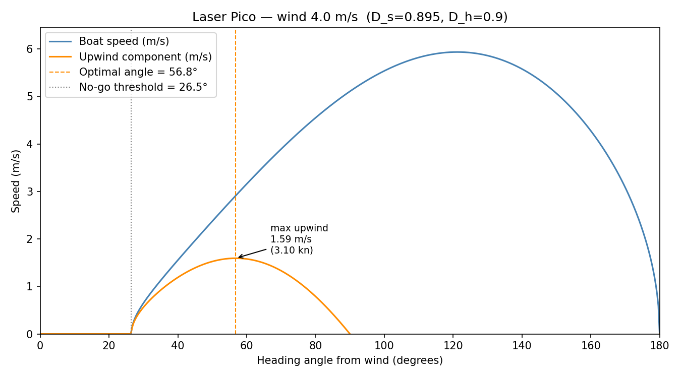
Boat speed and upwind component vs heading angle (Laser Pico, 4 m/s wind). The dashed line marks the optimal angle; the dotted line the no-go threshold.
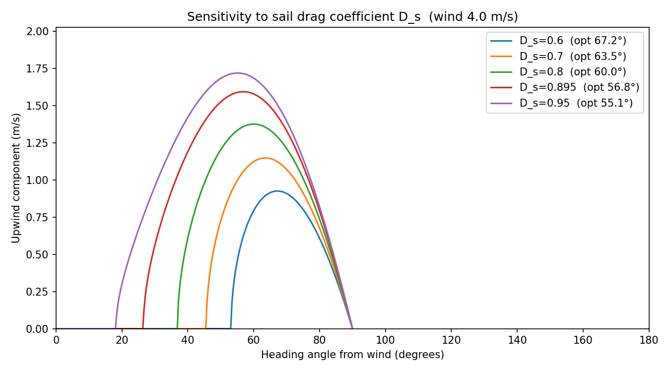
Upwind speed for five sail drag coefficients. A lower $D_s$ (slipperier sail) pushes the optimal angle further from the wind.
Diagrams


Left: top-down geometry at the optimal heading. Right: force diagram — propulsive sail force (blue) balanced by hull drag (red); the leeward push and centreboard reaction (grey, dashed) cancel and play no further role.
Python package
The full source is on GitHub.
All parameters live in config.yaml.
Configuration is managed by Hydra — any value can be overridden
on the command line without editing the file.
| Key | Meaning | Default |
|---|---|---|
wind.speed_ms |
True wind speed (m/s) | 4.0 |
coefficients.D_s |
Sail drag coefficient | 0.895 |
coefficients.D_h |
Hull drag coefficient | 0.9 |
boat.sail_area_m2 |
Sail area (m²) | 5.1 |
boat.hull_area_m2 |
Frontal underwater area (m²) | 0.0343 |
model.mode |
"one_deflector" or "two_deflector" |
"one_deflector" |
model.centreboard.area_m2 |
Centreboard planform area (m²) | 0.125 |
model.centreboard.aspect_ratio |
Centreboard AR = span²/area | 6.0 |
pip install -e ".[dev]"

# Generate all plots and diagrams with default parameters
python -m sailing_upwind

# Override any parameter on the command line (Hydra syntax)
python -m sailing_upwind wind.speed_ms=7
python -m sailing_upwind model.mode=two_deflector
python -m sailing_upwind model.centreboard.area_m2=0.20 model.centreboard.aspect_ratio=8

pytest   # 34 tests, including doctests
Repository layout
config.yaml                    ← all tuneable parameters (Hydra config)
sailing_upwind/
  model.py                     ← core physics (boat_speed, upwind_speed, optimal_angle)
  two_deflector.py             ← two-deflector model with finite centreboard
  config.py                    ← YAML loader + validation
  plots.py                     ← matplotlib figures (one- and two-deflector)
  diagrams.py                  ← geometry and force diagrams (SVG)
  __main__.py                  ← CLI entry point (@hydra.main)
tests/
  test_model.py                ← unit tests + physics sanity checks
  test_config.py               ← config validation tests
two-def.md                     ← two-deflector model derivation and results
.github/workflows/ci.yml
.github/workflows/pages.yml
Appendix: Full Derivation
Variables and notation
| Symbol | Meaning | Units |
|---|---|---|
| $\theta$ | angle between boat heading and wind | rad / ° |
| $v_s$ | true wind speed | m s⁻¹ |
| $v$ | boat speed | m s⁻¹ |
| $u$ | upwind component of boat speed | m s⁻¹ |
| $a_s$ | sail area | m² |
| $A_h$ | frontal underwater hull area | m² |
| $\rho_a$ | density of air | kg m⁻³ |
| $\rho_w$ | density of water | kg m⁻³ |
| $D_s$ | sail drag coefficient (fraction of wind speed retained after sail) | — |
| $D_h$ | hull drag coefficient (fraction of water speed retained after hull) | — |
Assumptions
- Close-hauled geometry. The sail lies along the boat’s central axis, so the angle of attack of the wind on the sail equals the heading angle $\theta$.
- No aerodynamic hull drag. Air resistance on the hull and crew is small compared with water drag and is ignored.
- Steady, uniform wind. Wind speed $v_s$ is constant in time and uniform across the sail — no gusts, no wind gradient with height.
- Infinite lateral resistance (this model only). The centreboard is assumed to prevent all sideways drift (leeway). Any leeward component of sail force is instantly cancelled by an equal centreboard reaction. Only the forward force balance matters. The two-deflector model removes this assumption.
- Flat, rigid sail. The sail presents a flat surface; the aerodynamics are treated purely through Newton’s laws (momentum conservation), not lift theory.
- Complete deflection. The sail redirects all air that passes over it to the boat’s axial direction — none escapes to the sides.
- Uniform speed reduction. The sail slows the deflected air to a fraction $D_s$ of its original speed ($0 < D_s < 1$). $D_s = 1$ is a perfectly frictionless sail that changes direction without losing speed; $D_s = 0$ brings the air to rest. Measured values for small dinghies cluster around $0.85$–$0.92$.
- Quadratic hull drag. Drag $= (1-D_h)\,\rho_w\,A_h\,v^2$, i.e. the hull removes a fraction $(1-D_h)$ of the momentum of water passing its frontal area per second. This is the same momentum-flux model applied to water.
Step 1 — How much air does the sail intercept?
Set up coordinates with the wind blowing in the $-y$ direction and the boat heading at angle $\theta$ from the wind. The sail has area $a_s$ and lies along the boat’s axis.
The sail presents a projected cross-section $a_s|\sin\theta|$ perpendicular to the wind. (At $\theta = 0°$ the boat faces directly into the wind and the sail presents zero area; at $\theta = 90°$ the full sail area faces the wind.)
In one second a column of air of length $v_s$ sweeps past this cross-section. Its volume is:
\[V = v_s \cdot a_s |\sin\theta|\]Its mass is $m = \rho_a V = \rho_a a_s v_s |\sin\theta|$, so the momentum flux (momentum delivered to the sail per second, i.e. force available from the airstream) is:
\[\Upsilon = m \cdot v_s = \rho_a \, a_s \, v_s^2 \, |\sin\theta|\]Step 2 — Force from the sail: decomposing momentum change
The wind arrives travelling in the $-y$ direction (straight downwind) at speed $v_s$. After hitting the sail the air is redirected to travel along the boat’s forward axis at the reduced speed $D_s v_s$.
To find the net forward force we compute the change in the air’s momentum along the boat’s forward direction.
Set up unit vectors. Define forward as the $+x’$ direction (the boat’s axis). The boat heads at angle $\theta$ from the wind, so the forward unit vector in world coordinates is $\hat{f} = (\sin\theta,\, \cos\theta)$.
Incoming forward momentum flux. The wind velocity in world coordinates is $(0,\,-v_s)$. Its component along $\hat{f}$ is:
\[v_\text{in,fwd} = (0,-v_s)\cdot(\sin\theta,\cos\theta) = -v_s\cos\theta\]The minus sign means the wind blows against the boat’s heading when $\theta < 90°$ — as expected when sailing upwind.
Outgoing forward momentum flux. After the sail deflects the air, it leaves along the forward axis at speed $D_s v_s$:
\[v_\text{out,fwd} = +D_s v_s\]Change in forward velocity per unit mass of air:
\[\Delta v_\text{fwd} = v_\text{out,fwd} - v_\text{in,fwd} = D_s v_s - (-v_s\cos\theta) = v_s(D_s + \cos\theta)\]Multiplying by the mass flux $\dot{m} = \rho_a a_s v_s|\sin\theta|$ from Step 1, Newton’s second law gives the force that the sail exerts on the air. By Newton’s third law, the air exerts an equal and opposite force on the sail, driving the boat forward:
\[F_\text{sail} = \dot{m}\,\Delta v_\text{fwd} = \rho_a a_s v_s^2|\sin\theta|(D_s + \cos\theta)\]The no-go zone. This result implies positive drive for all $\theta \in (0°,90°)$, which is wrong — every real boat refuses to sail close to the wind. The issue is that the formula above assumed the exiting air always travels forward along the boat axis. That is only geometrically possible if the sail can redirect air arriving nearly head-on; for small angles the physical constraint is that the sail can only push air aft of the beam.
The correct constraint is that the incoming airstream, which has a forward component $-v_s\cos\theta$ (pointing aft), can only be redirected so that the net forward push is positive. This is possible only if:
\[D_s v_s - v_s\cos\theta > 0 \quad \Longrightarrow \quad \cos\theta < D_s \quad \Longrightarrow \quad \theta > \arccos(D_s)\]In this region the deflected air does exit with a forward component (it was pointing aft, so the sail must do enough work to reverse that component and provide $D_s v_s$ forward). Replacing the earlier $+\cos\theta$ term with $-\cos\theta$ to reflect this geometry:
\[\boxed{F_\text{sail} = \rho_a \, a_s \, v_s^2 \, |\sin\theta|\,(D_s - \cos\theta)}\]This is positive only when $\theta > \arccos(D_s)$. For $D_s = 0.895$ the no-go boundary is $\arccos(0.895) \approx 26.5°$, consistent with the $\sim45°$ empirical no-go zone of real dinghies (the model understates the no-go zone because it ignores stall and hull aerodynamics, which reduce effective $D_s$).
What about the leeward component?
The incoming air also carries momentum across the boat. The transverse momentum
transferred to the boat per second is $\Upsilon\sin\theta$, pushing the boat leeward.
By assumption 4 the centreboard reacts with an equal and opposite force, so the
lateral equation is automatically satisfied and plays no further role.
Step 3 — Hull drag
The hull moves through water at speed $v$. By the same momentum-flux argument as step 1 (applied to water instead of air), the water drag force opposing forward motion is:
\[F_\text{drag} = (1-D_h)\,\rho_w\,A_h\,v^2\]Here $(1-D_h)$ is the fraction of the water’s forward momentum that is removed (i.e. transferred to the hull as drag) as the hull passes through. $D_h = 0.9$ means the hull is fairly streamlined — it only takes 10% of the momentum of the water column it displaces.
Step 4 — Terminal boat speed
At steady state the boat accelerates until the propulsive and drag forces balance. Setting $F_\text{sail} = F_\text{drag}$:
\[\rho_a \, a_s \, v_s^2 \, |\sin\theta|(D_s - \cos\theta) = (1-D_h)\,\rho_w\,A_h\,v^2\]Solving for $v$:
\[v^2 = \frac{\rho_a \, a_s \, v_s^2 \, |\sin\theta|(D_s - \cos\theta)}{(1-D_h)\,\rho_w\,A_h}\] \[\boxed{v(\theta) = v_s\sqrt{\frac{\rho_a \, a_s \, |\sin\theta|(D_s - \cos\theta)}{(1-D_h)\,\rho_w\,A_h}}}\]Notice that $v \propto v_s$ — the boat speed scales linearly with wind speed, as observed in practice. All other factors are geometric or material constants.
Dimensional check:
\[[v] = \text{m\,s}^{-1} \cdot \sqrt{\frac{(\text{kg\,m}^{-3})(\text{m}^2)}{(\text{kg\,m}^{-3})(\text{m}^2)}} = \text{m\,s}^{-1}\cdot\sqrt{1} = \text{m\,s}^{-1} \checkmark\]Step 5 — Upwind velocity component
We want to maximise upwind progress, not raw speed. The component of boat velocity directed straight into the wind is:
\[u(\theta) = v(\theta)\cos\theta\]Substituting the expression for $v(\theta)$:
\[u(\theta) = v_s\cos\theta\sqrt{\frac{\rho_a a_s \sin\theta(D_s - \cos\theta)}{(1-D_h)\rho_w A_h}}\]Since the square root is always positive and $v_s$ is a positive constant, maximising $u$ is equivalent to maximising:
\[u^2(\theta) = \underbrace{\frac{\rho_a a_s v_s^2}{(1-D_h)\rho_w A_h}}_{\textstyle C\ (\text{const w.r.t.}\ \theta)} \cdot \underbrace{\cos^2\theta \cdot \sin\theta \cdot (D_s - \cos\theta)}_{\textstyle f(\theta)}\]So we need to find $\theta$ that maximises $f(\theta) = \cos^2\theta\,\sin\theta\,(D_s - \cos\theta)$.
Step 6 — Finding the optimal angle
Substitution. Let $x = \cos\theta$, so $\sin\theta = \sqrt{1-x^2}$ and $\sin^2\theta = 1 - x^2$. We need $f’(\theta) = 0$.
It is easier to differentiate $f$ with respect to $\theta$ directly and then substitute $x = \cos\theta$ afterward.
Expand $f$:
\[f(\theta) = \cos^2\theta\,\sin\theta\,D_s - \cos^3\theta\,\sin\theta\]Differentiate using the product rule. Recall $\tfrac{d}{d\theta}(\cos\theta) = -\sin\theta$ and $\tfrac{d}{d\theta}(\sin\theta) = \cos\theta$:
\[\frac{df}{d\theta} = \frac{d}{d\theta}\!\left[D_s\cos^2\theta\sin\theta\right] - \frac{d}{d\theta}\!\left[\cos^3\theta\sin\theta\right]\]For the first term, let $g = \cos^2\theta$ and $h = \sin\theta$:
\[\frac{d}{d\theta}[D_s g h] = D_s(g'h + gh') = D_s\!\left(-2\cos\theta\sin^2\theta + \cos^3\theta\right)\]For the second term, let $g = \cos^3\theta$ and $h = \sin\theta$:
\[\frac{d}{d\theta}[gh] = g'h + gh' = -3\cos^2\theta\sin^2\theta + \cos^4\theta\]Combining:
\[f'(\theta) = D_s\!\left(\cos^3\theta - 2\cos\theta\sin^2\theta\right) - \left(\cos^4\theta - 3\cos^2\theta\sin^2\theta\right) = 0\]Factor out $\cos\theta$ (we are looking for $0 < \theta < 90°$, so $\cos\theta > 0$ and this is valid):
\[D_s\!\left(\cos^2\theta - 2\sin^2\theta\right) - \cos\theta\!\left(\cos^2\theta - 3\sin^2\theta\right) = 0\]Substitute $x = \cos\theta$, $\sin^2\theta = 1 - x^2$:
\[D_s\!\left(x^2 - 2(1-x^2)\right) - x\!\left(x^2 - 3(1-x^2)\right) = 0\] \[D_s\!\left(3x^2 - 2\right) - x\!\left(4x^2 - 3\right) = 0\] \[3D_s x^2 - 2D_s - 4x^3 + 3x = 0\]Rearranging into standard form:
\[\boxed{4x^3 - 3D_s\,x^2 - 3x + 2D_s = 0 \qquad (x = \cos\theta_\text{opt})}\]Key insight: this cubic contains only $D_s$. The optimal heading is independent of wind speed, boat size, sail area, and hull parameters — it depends solely on how efficiently the sail deflects air. This is a surprisingly clean result for what appears to be a complicated optimisation.
Selecting the physical root. The cubic has three real roots when $D_s \in (0,1)$. The physically meaningful root is the one satisfying:
- $0 < x < D_s$ (boat is heading outside the no-go zone, $\theta > \arccos(D_s)$, and $\theta < 90°$)
- $x = \cos\theta > 0$ (heading in the upwind half, $\theta < 90°$)
The other two roots correspond to mathematical solutions with no physical meaning (e.g. $\theta > 90°$ or inside the no-go zone).
Step 7 — Results for the Laser Pico
| Parameter | Symbol | Value |
|---|---|---|
| Wind speed | $v_s$ | 4 m/s (7.8 kn) |
| Sail area | $a_s$ | 5.1 m² |
| Hull frontal area | $A_h$ | 0.0343 m² |
| Sail drag coefficient | $D_s$ | 0.895 |
| Hull drag coefficient | $D_h$ | 0.9 |
| Air density | $\rho_a$ | 1.225 kg m⁻³ |
| Water density | $\rho_w$ | 1000 kg m⁻³ |
Substituting $D_s = 0.895$ into the cubic $4x^3 - 3(0.895)x^2 - 3x + 2(0.895) = 0$
and solving (e.g. with numpy.roots) gives three roots approximately:
$x \approx {-0.831,\; 0.459,\; 0.547}$.
The root $x \approx -0.831$ corresponds to $\theta \approx 146°$ (well past beam-reach — not a useful upwind course). The root $x \approx 0.459$ gives $\theta \approx 62.7°$, outside the range $0 < x < D_s$ physically (it is a local minimum of $u$, not a maximum). The root $x \approx 0.547$ gives:
\[\theta_\text{opt} = \arccos(0.547) \approx 56.8°\]Substituting back:
\[v_\text{opt} = 4\sqrt{\frac{1.225 \times 5.1 \times \sin(56.8°)\times(0.895 - \cos(56.8°))}{0.1 \times 1000 \times 0.0343}} \approx 2.86 \ \text{m/s}\] \[u_\text{max} = v_\text{opt}\cos(56.8°) \approx 2.86 \times 0.547 \approx 1.60 \ \text{m/s} \approx 3.1 \ \text{knots}\]Bibliography
-
T. W. Körner (1996). The Pleasures of Counting. Cambridge University Press. (Inspiration for the dimensional-analysis approach.)
-
V. Radhakrishnan (1997). From Square Sails to Wing Sails: The Physics of Sailing Craft. Current Science, 73(6). (Link no longer available.)
-
B. D. Anderson (2008). The Physics of Sailing. Physics Today. Link
-
J. Wolfe (2002). The physics of sailing. University of New South Wales. Link